Tissuealign
The Tissuealign article contain information about aligning images. It provides information regarding import of data, linking images, review/correct the alignments and how to apply a protocol to the images.
If both Tissuealign and Tissuearray are installed, the VirtualDoubleStaining (VDS) module can be used. VDS is a novel and patent protected method for automated, robust and verifiable tumor and stroma separation in Tissue Microarrays (TMAs) and whole tissue sections.
Linking images
After selecting suitable images and importing them into a folder in the database, they can be linked. Linking of the images must be done before automatic alignment can be performed.
To link images, select an image and Alt + click another image in the database to view the images side by side. Any number of images can be selected this way. Once the desired number
of images is selected, proceed to correcting the alignment.
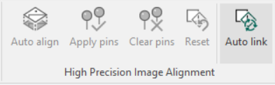
Clicking the Auto Link button in the ribbon will open the Automatic Linking dialog, which will enable linking of images based on the names of the files. There are two main methods for defining the pattern which describes the images to be linked, Delimited and Fixed Length.
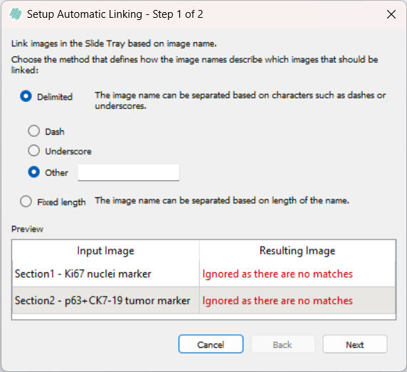
Using the Delimited option, either a dash "-", an underscore "_", or a custom delimiter can be chosen to select which input images will be linked. The custom delimiter is case sensitive and should be a single character. The last appearing delimiting character will be used to select the images. If an image will not be linked using the currently selected pattern, a warning will be displayed reading "Ignored as there are no matches".
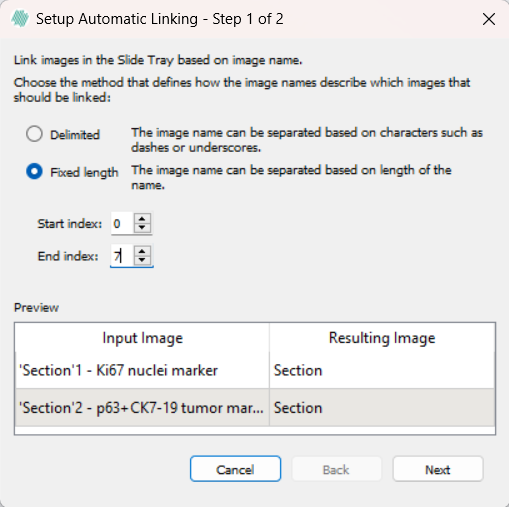
The Fixed Length option has two inputs, start index and end index. Each image where the name is equal between the indexes will be selected for linking. If both indexes exceed the length of the names, the images will be treated as having the same text between the indexes, and will be linked.
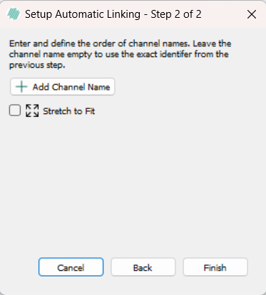
After selecting a method for linking images, there is an option to either retain the default channel name generated by the method or rename the channel by clicking the Add Channel Name button. Selecting Finish prompts a save window, allowing selection of an appropriate location to save the autolinked image.
The image is now available in the saved location. Scroll through the image and its attached channels or segmentation masks by pressing the Page Up and Page Down keys.
Tissuealign Multiview Without Alignment.
Multiview can be enabled in Tissuealign, and the image stack can be saved without performing alignment by pressing  followed by saving. This creates a “zero transform” WSS file that links the images without modifying their positions.
This feature is useful when importing images or overlays (e.g., TIFF masks) that share the same dimensions but do not have spatial calibration or offsets.
followed by saving. This creates a “zero transform” WSS file that links the images without modifying their positions.
This feature is useful when importing images or overlays (e.g., TIFF masks) that share the same dimensions but do not have spatial calibration or offsets.
Review and correct alignment
Each aligned slide should be reviewed to determine if alignment correction is needed. This review can be conducted by navigating through the linked images using the Page Up and Page Down keys. If the review indicates that the initial alignment is insufficient, there are two options for correction:
| Option | Description |
|---|---|
 | Automatic alignment based on current pin points (Semi-automatic alignment). Selecting this option will align the images based on the placed pin points, and then do a more detailed alignment using the built-in automatic aligner. |
 | If no pins are palced, this button replaces the Automatic alignment based on pin points button. |
 | Apply current pin points to image (Manual alignment). This alignment option will use only the pin points to align the images. |
In both cases it is recommended to place at least 3 pairs of pins on notable locations in the image to reach a good final alignment. When choosing notable locations in the tissue, avoid placing pins in edge regions of the tissue, as there is a risk of this tissue being damaged. When placing a pin in one image, a corresponding pin must be placed in other images of the alignment. If multiple pins are placed in a row in one image, the corresponding pins must be placed in the same order in other images.
When finding notable locations in the tissue slides activating or deactivating image viewing lock might be an advantage.
This can be done ensuring the  button is clicked (it is enabled by default). The viewing of the linked can be reset to the default view by clicking the
  button.
Tissuealign also provides 3 helpful tools to ease the correction process:
| Tool | Description |
|---|---|
Ctrl+Z | Undoes only the last pin point added to an image, allowing correction of misplaced pin points. Multiple pin points can be undone sequentially by clicking the shortcut repeatedly. |
Deletes all pin points added to all currently displayed images. Use this tool only if certain about removing all pin points. Pressing Ctrl + Z will undo the deletion and restore all pins. | |
 | Use this tool to undo an unsuccessful alignment. For example, if a manual alignment is applied but the previous automatic alignment provided better results, return to the automatic alignment by undoing the manual alignment. |
Review the alignment to determine if further correction is necessary. If the alignment remains insufficient, consider increasing the number of pin points.
Alignment using ROIs
Alignment can also be done using ROIs. This is especially useful if dealing with damaged tissue that requires exclusion from the alignment process.
To align two or more images using ROIs, simply draw any type of ROI around the relevant tissue(s) in each image and click Auto align. When ROIs are present, aligment will only be performed based on pixels that are inside ROIs.
For aligning regions within a single image, multiple versions of the image need to exist in the database. This can be achieved by duplicating the image with a different name or saving it in a different location in the database. Alternatively, following the Tissuearray workflow to dearray tissues in the image will also allow for the creation of multiple images in the database. Once multiple images exist in the database, the above workflow can be employed to align them.
Selecting the Reference Image for Accurate Alignment
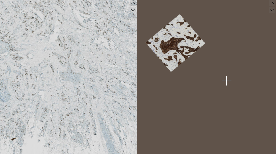
To achieve precise alignment of smaller Field of View (FOV) images on Whole Slide Images (WSI) in the Tissuealign module, it is essential to select the FOV image as the reference image first. Choosing the incorrect reference can lead to unpredictable results, even when using alignment pins.
When the FOV image is selected as the reference, it ensures a properly scaled alignment, preserving details and proportions in relation to the larger WSI. This practice is particularly relevant in the following scenarios:
- IMC ROIs on Akoya WSIs
- Nanostring ROIs on H&E WSIs
Step-by-Step: How to Select FOV as the Reference Image
- Open the Tissuealign module.
- Select the FOV image first as the reference image to ensure alignment accuracy.
- Continue with the alignment process as instructed in the module.
Risks of Incorrect Reference Selection
Selecting the WSI image as the reference may lead to alignment errors. FOV images are smaller and contain details that can misalign with the WSI, potentially resulting in a shifted final output. To prevent this, it is crucial to select the FOV as the reference image.
Example: Visualizing Reference Selection
- WSI as reference (incorrect)
- FOV as reference (correct)
By following these steps and selecting the FOV as the reference image first, the best accuracy in alignment is achieved.
It is possible to export a transformed stack using "Export de-identified image" under Files, which will save the reference image and any aligned images. If WSS fusion is activated, the fused image will also be saved.
Processing of alignment
Once the alignment is sufficient, ensure that the alignment is saved. An APP or a series of APPs can now be run on the aligned images and the output of the APPs will be visible on all parts of the alignened images which can be viewed by pressing the Page Up and Page Down keys.
Most default APPs will only run on one of the aligned images. Changing which image the APP should run on can be done in the APP Author in the Classification tab.
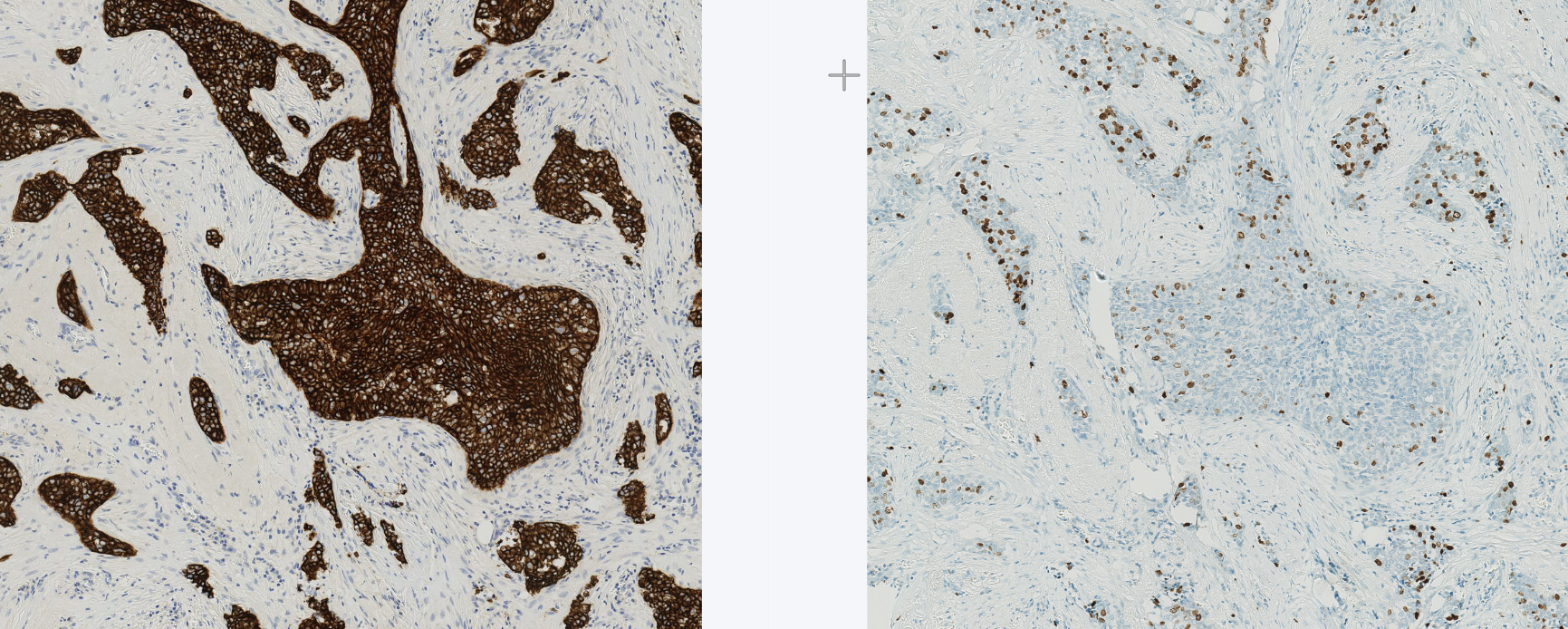
Visualizing All Channels of Multiplex Images in Tissuealign
The Visualizing All Channels feature in Tissuealign enables users to view all co-registered multiplex imaging channels in a single, aligned dataset. This provides a clearer overview of spatial marker distribution, improving analysis accuracy and efficiency. Users can easily toggle, manage, and organize channels for a more streamlined workflow.
Integrated Channel Viewing
- All imaging channels are combined into a newly aligned image, appended at the end of the image sequence.
- View all channels simultaneously, improving visualization and usability.
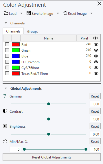
Channel Adjustment Tool
To visualize all channels of multiplex images in Tissuealign, follow these steps:
Align the images in Tissuealign:
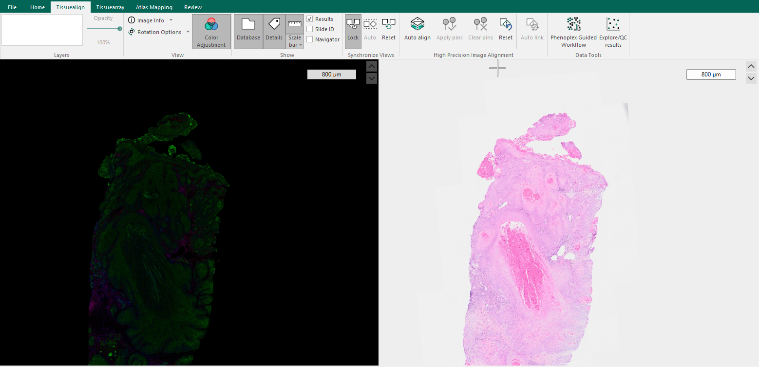
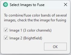
Save the aligned image and select both images to fuse the color channels.
Use the Color Channel Adjustment tool to toggle channels on and off for focused inspection.