Tissuearray
The Tissuearray articles contain information about obtaining the individual and aligned cores from TMA ("Tissue Micro Arrays") virtual slides. It provides information regarding setup and review extraction.
While dearraying TMA slides is the main application, these tools can also be used to split multi-tissue slides, or subsample regions of a single piece of tissue.
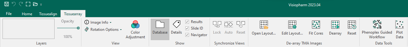
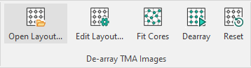
The module can be accessed by clicking the tab in the ribbon. After a suitable image is selected from the database, the next step is to select the TMA layout.
Setup a new grid
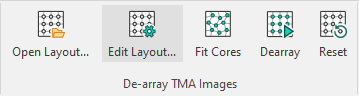
The Edit Layout... button opens a dialog making it possible to create a TMA layout, mark cores as active or invalid, specify IDs to the cores, etc.
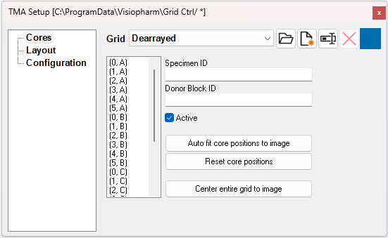
This launches the TMA setup dialog box:
| Button | Action |
|---|---|
| Load a TMA layout. | |
| Adds a new grid. | |
| Rename the selected grid. | |
| Delete the selected grid in the list. | |
 | Change color of templates and grid (appears only when a template has been created/loaded. The chosen color is displayed as the icon). |
Cores
Cores makes it possible to specify an ID for each core, mark the individual cores as active or non-existing/invalid, and change the core positions of the grid.
Naming of Cores
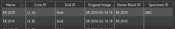
The name under Details of each core after they are saved to the database will be the coordinate concatenated with the Donor Block ID. If a core has no Donor Block ID, the name will be the coordinate concatenated with the Specimen ID. Both the Donor Block ID and the Specimen ID are saved to the cores in the Database.
If desired, the cores can be named soley by their Donor Block ID. To do so, open the following folder in the registry editor;
Computer\HKEY_LOCAL_MACHINE\SOFTWARE\Visiopharm\VPSDK
and create a REG_DWORD key by right-clicking and pressing new. Name it Name Core by Donor Block ID and set the data value to 0x00000001 (1) . It should look like this:
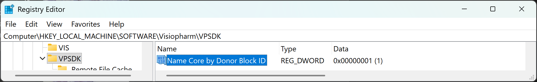
Below is an example of what it will look like in the database.
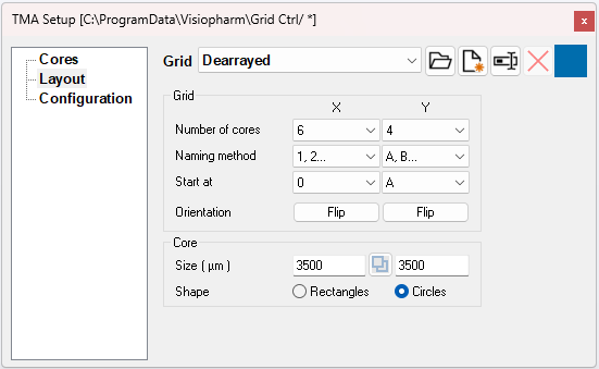
Layout
Layout can be used when defining a new grid. It is possible to define number of cores, naming method, orientation, core size, and core shape.
| Input | Action |
|---|---|
| Number or cores | Set the number of cores in the x- and y-axis. |
| Naming method | Choose between different numbering styles on the x- and y-axis. |
| Start at | Choose the first number to start at when counting. |
| Orientation | Choose to flip either or both axis. |
| Size | The size of each core diameter. |
 | Link or unlink the sizes height and width axes. |
| Shape | Choose between an elliptical or rectangular core shape. |
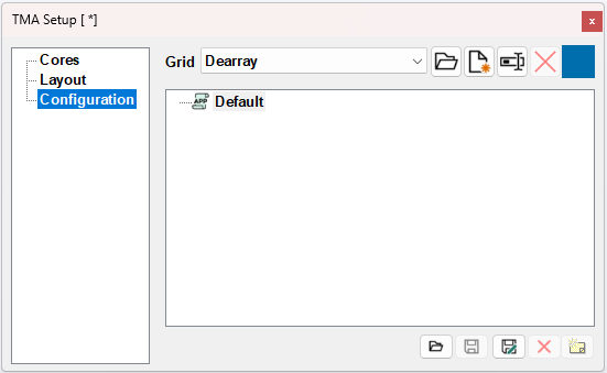
Configuration
Configuration makes it possible to save and load configurations.
Load TMA layout from a file
The Open Layout... button allows for loading an already existing layout file e.g. exported directly from the scanner or 3rd party software.
The module supports the following types of files for a TMA layout:
- Visiopharm TMA Layout File (*.csv)
- Galileo TMA Layout File (*.xml)
- 3DHisTech TMA Layout File (*.xls)
- 3DHisTech Grand Master Layout File (*.xml)
- Beecher TMA Layout File (*.seq)
Visiopharm TMA layout
The Visiopharm TMA Layout file is a csv.-file that can be created in any text editing software that supports the csv.-file format. The Visiopharm TMA Layout file has a very simple layout format and includes only 7 variables:
- Name - Name of the TMA grid.
- Rows - Number of rows in the entire grid.
- Cols - Number of columns in the entire grid.
- Diameter - Diameter of each core in m.
- R - A column where each entry is the row number of a specific core in the grid.
- C - A column where each entry is the column number of a specific core in the grid.
- ID - A column where each entry is the specimen ID of a specific core.
The csv file containing the layout needs to be comma separated ',' and nothing else.
The file must be saved in the old MS-DOS (ANSI) format and not in other formats.
Example of a Visiopharm TMA layout file
Below is an example in which the grid is named "My Visiopharm Grid" and has 2 rows and 3 columns where each core has a diameter of 2500 m. The individual cores have IDs from "D001" to "D012", e.g. core in (row (R) 1, column (C) 1) has ID "D001".
Name,Rows,Cols,Diameter
My Visiopharm Grid,1,3,2500
R,C,ID
1,1,D001
1,2,D002
1,3,D003
2,1,D004
...
Download example .csv file
All entries in the grid must be explicitly defined.
The layout must represent a complete grid as declared by the Rows and Columns values — every combination of row and column must be populated. Missing or partial grids will result in failure to load the file.
Link to download an example .csv file: Visiopharm TMA Layout file example
3DHistech TMA layout
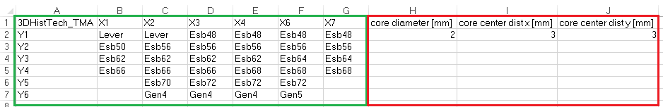
The 3DHisTech TMA Layout file requires input of three TMA parameters in the Excel sheet before loading and using the layout file in Visiopharm.
- Open the 3DHisTech TMA Layout file (.xls) in Microsoft Excel.
- Select the sheet containing "_B".
- Add the following parameters as columns.
- Core diameter [mm] in row 2 in the first column right of the TMA layout.
- Core center dist x [mm] in row 2 in the second column right of the TMA layout. This is the distance between each core from center to center on the x-axis.
- Core center dist y [mm] in row 2 in the third column right of the TMA layout. This is the distance between each core from center to center on the y-axis.
- Save and close the file.
The 3DHisTech TMA Layout file can now be imported into Visiopharm. These steps are not needed for 3DHistech Grand Master layout files.
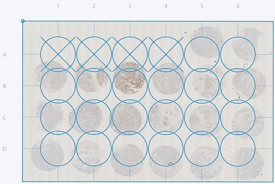
Adjusting grid and deactivating cores
The grid can be adjusted by scaling and rotation. Click, hold and move the corners of the grid to scale and rotate at the same time. Scaling without rotation can be done by dragging the edges of the grid.
The grid frame can be moved by placing the cursor in the area between cores and dragging. It is possible to move an entire column or row by dragging the letter or number indicating the row/column.
Deactivate/remove non-existing cores from the grid by double-clicking on the given cores or by marking them as inactive in the cores tab of the TMA setup menu.
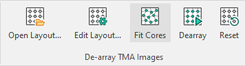
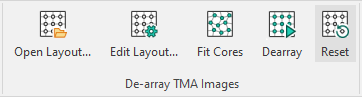
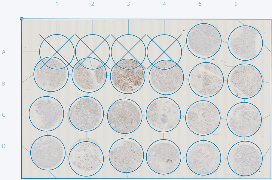
Fit cores to image and reset core positions
The Fit Cores option fits the current grid to the cores. After fitting it is possible to manually correct the grid further by dragging indivudual cores. Entire rows or columns can be moved by clicking and dragging the letter or number next to the given row or column.
Clicking the Reset button resets the grid to a rectangle with equally spaced cores.
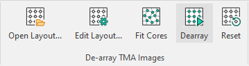
Extraction and review
The next step in the Tissuearray workflow is to Dearray the cores to extract them. This will create a subfolder in the working directory named after the file to be dearrayed. This folder will contain an image for each core, named as the name of the grid and the position of the core in the grid.
It is recommended to inspect each of the extracted cores to verify that the tissue has been extracted correctly.
Virtual double staining - VDS
VirtualDoubleStaining (VDS) is a novel and patent protected method for automated, robust and verifiable tumor and stroma separation in Tissue Microarrays (TMAs) and whole tissue sections. Alignment of a e.g. a tumor marker (e.g. PCK, H&E, CK5/CK7+P63, etc) to analytical marker enables the tumor marker to become a region of interest on the analytical marker. This provides verifiable, automated identification of tumor cells. Therefore, pathologists do not need to manually outline or identify the tumor areas. However, the method can be used on any two or three different images of the same tissue section.
VDS utilizes the Tissuealign module, i.e. users are only enabled to add VDS capabilities to the Tissuearray workflow if Tissuealign is installed.
Image linking
The first step is to ensure that at least two suitable images have been imported into the Database. These images should contain cores with different stainings for the initial images.
Open the Tissuealign module by clicking the button in the ribbon. Then the images should be linked as described in the Tissuealign article. The images containing multiple cores should in this case not be treated as multiple images, but as one.
Reviewing and correcting alignment
As when linking a single core, the alignment should be reviwed and optionally corrected by placing pins. A guide for correcting the alignment can be found in the Tissuealign article.
Setup or load TMA
A TMA grid can then be setup as specified in the Setup a new grid section or can be imported from a file as specified in the Load TMA layout from a file section.
Adjust and fit grid
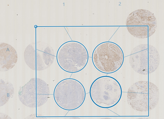
Now open the Tissuearray module by clicking the button in the ribbon. The grid that is used for one of the images can be used for the remaining images. When chosing a grid ensure that cores visible in one image are also visible in other images. This is easily done by using the Page Up and Page Down keys.
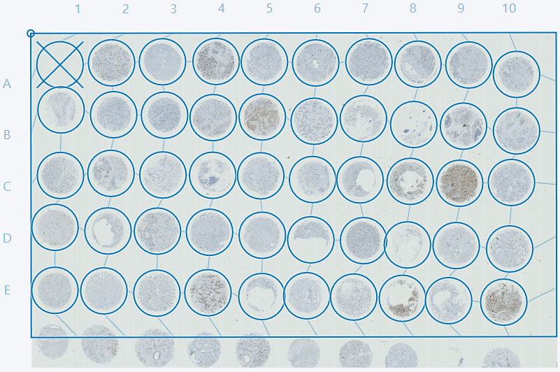
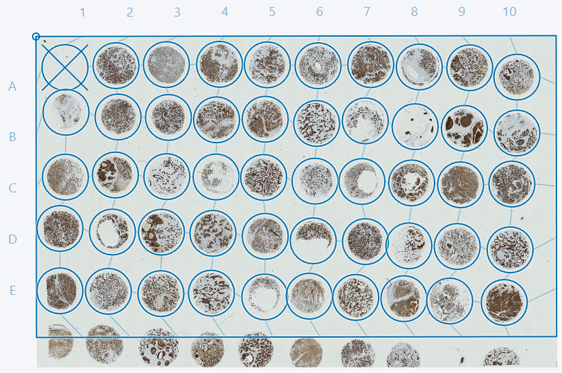
If some cores are cutoff, as in the example above, it is advised to deactivate these cores either by double-clicking or by ticking the box in the TMA setup dialog in the Cores tab. In this example we advise deactivating cores 1D and 1E. The cores can then be adjusted as described in the sections Adjusting grid and deactivating cores and Fit cores to image and reset core postions.
Dearray and review alignment
Finally the cores should be dearrayed by clicking the Dearray button. This will result in a dialog like the one seen below.
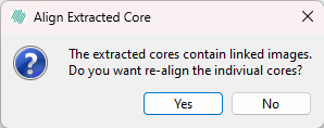
By clicking yes in the dialog, the individual cores will be realigned using the built-in alignment tool which is recommended, but more computationally heavy than clicking no, which will skip this alignment step.
The alignment of resulting dearrayed cores should then be reviewed and optionally corrected, as specified in the Tissuealign article.
Processing
Once the alignment is sufficient, ensure that the aligment is saved. An APP or a series of APPs can now be run on the aligned images and the output of the APPs will be visible on all parts of the alignened images which can be viewed by pressing the Page Up and Page Down keys.
Most default APPs will only run on one of the aligned images. Changing which image the APP should run on can be done in the APP Author in the Classification tab.